Openings & Ventilation
Image Gallery




Project Logs
February 6, 2012
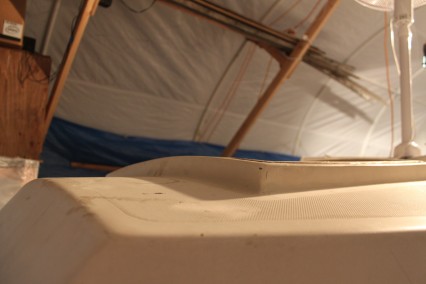
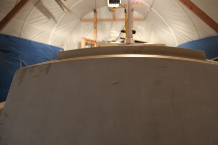
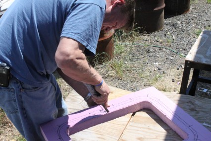
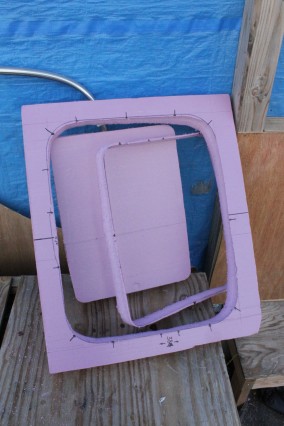
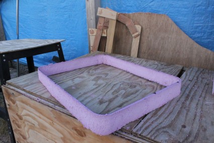
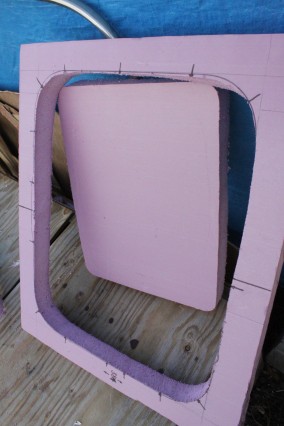
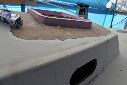
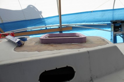
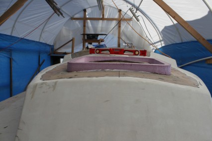
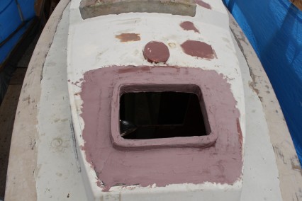
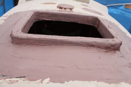
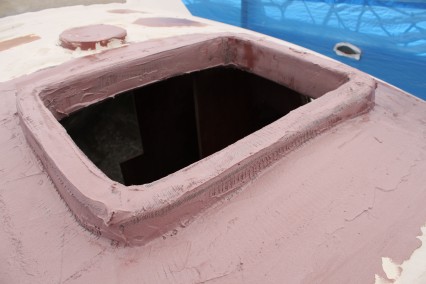
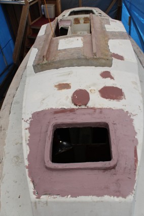
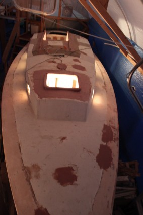
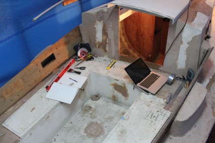
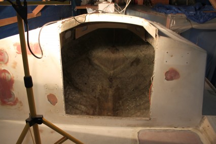
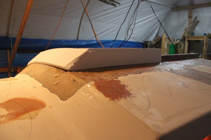
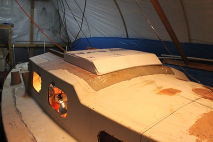
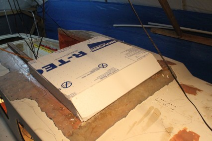
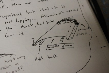
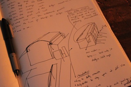
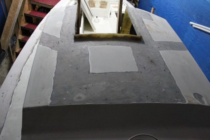
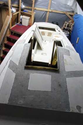
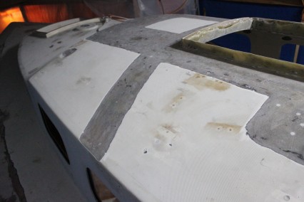
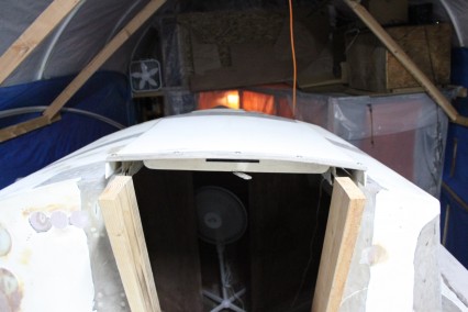
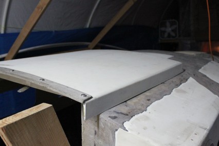
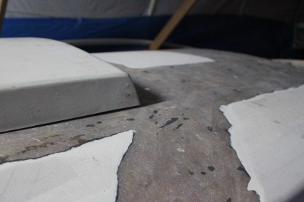
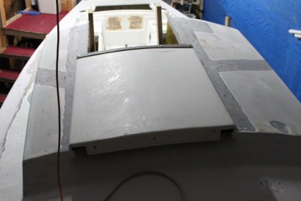
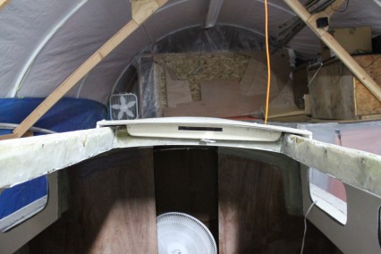
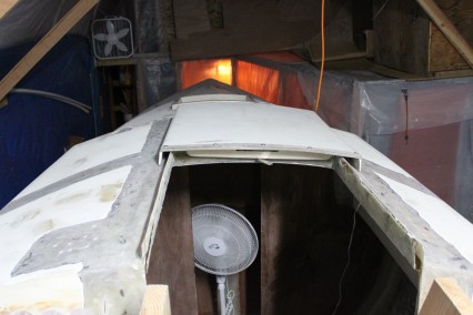
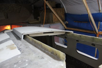
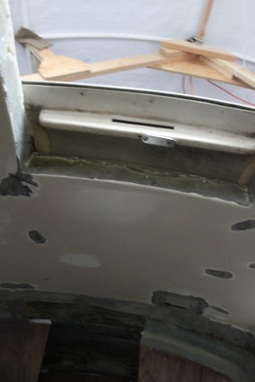
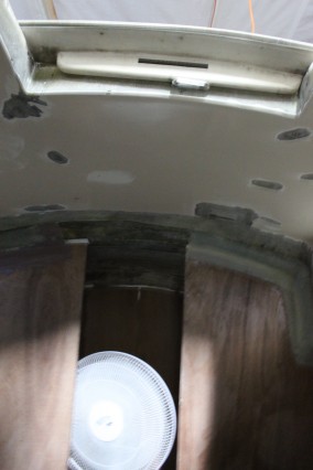
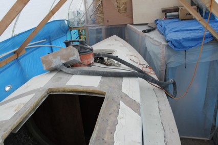
Work continues on the cockpit, but along the way I am giving consideration as to how the seahood construction will come together. I think it will start with a mold of the top of the hood, followed by construction of the sides and face. That being said, I will have to do some hands on work with this area before I will finally determine how the construction will come to be.
December 28, 2011
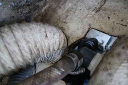
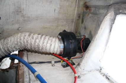
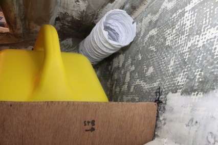
The below deck engine ventilation routing is complete. The next task will be to build below deck dorades and drill through deck vent holes, but this step won’t come for some time, as I will complete this step during construction of the cockpit combings. Some decisions I made during the installation differed a bit from the research I completed last winter. Here’s some highlights:
- Originally, I was going to use 5″ pipe (ABS or PVC) to match the ventilation of Vetus’ ATH0S1 mushroom ventilator (4 13/16″ opening dia.). However, I decided to use the Vetus PORT0S1 (3 11/32″ opening dia.). By using the smaller, PORT0S1 ventilator, it allowed me to use 3.5″ ABS piping which was more reasonably priced and would allow 4″ ventilation hose to be installed over the pipe. The smaller mushroom vent also had a smaller foot print on deck. Obviously the decision couldn’t be made without first relating the vent size to the required air flow which will properly ventilate the engine. This is a calculation based on the Cubic Feet per Minute (CFM) that needs to flow to the engine while running. Trouble is, I never seem to have gotten a straight answer on this in my research due to a variety of misunderstandings. One is that Vetus measures their air intakes as “free flow area” versus (what I consider to be) the standard of CFM. Further, contacting Beta about the CFM also proved to be a fruitless discussion. What I eventually landed on is that if 4″ is the largest diameter hose vent most commonly sold, it must be good enough for general use. Therefore, I will go with this 4″ size and the mushroom vents to match. Further, my calculations in the “Questions” section below seem to indicate that the PORT0S1 mushroom vents should work to properly vent the engine room, though my trust in those results is a little flimsy.
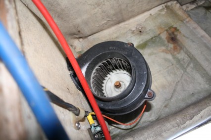
- From my research, I was going to originally going to add 12V fans to the ventilation run, but I decided against this to simplify the installation. I can always add them later if I find my engine room this ventilation is creating engine compartment temperatures in excess of 60°C.
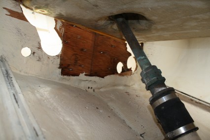
- I decided to add a section of hose in at the high point between the lazarette and cockpit bulkheads, because it would be lighter than an all pipe run and would also allow me to access the middle of the ventilation run should I ever need to do so.
With the key changes understood, let me go into some further detail about the process I went through to add the below deck engine ventilation routing:
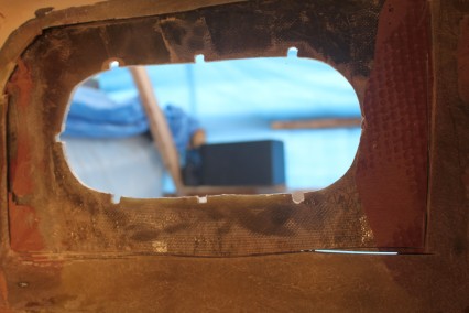
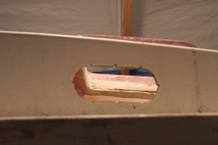
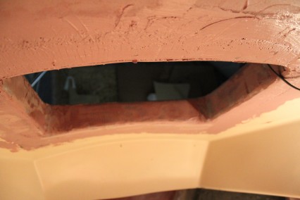
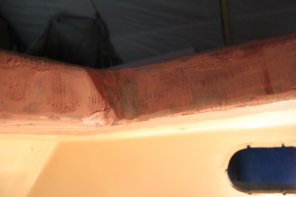
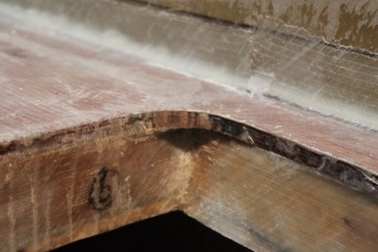
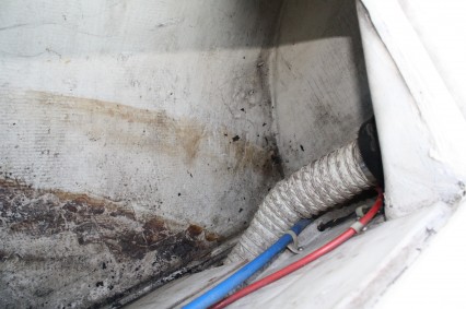
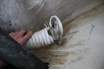
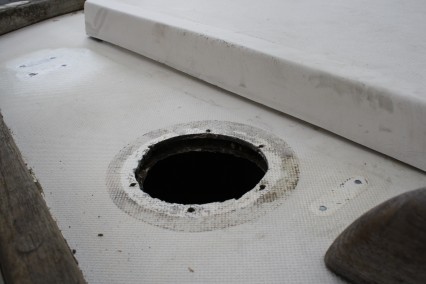
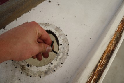
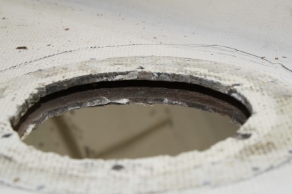
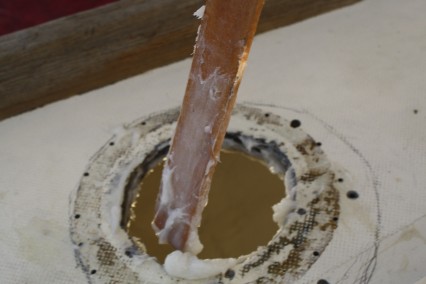
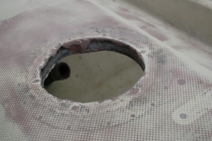
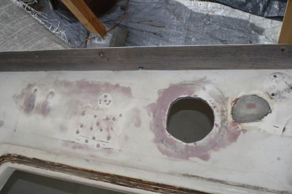
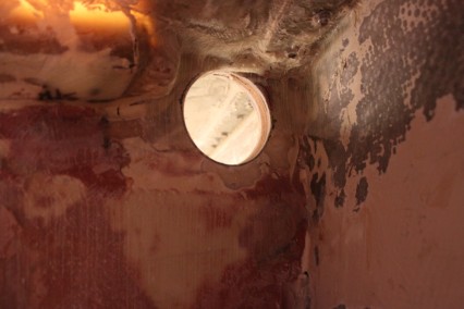
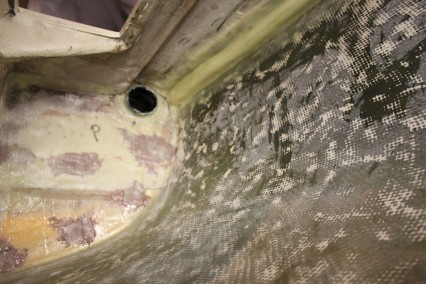
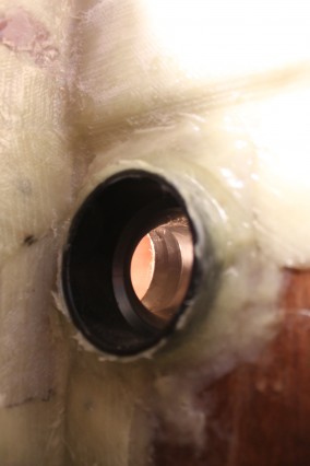
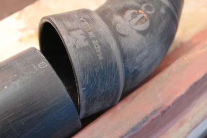
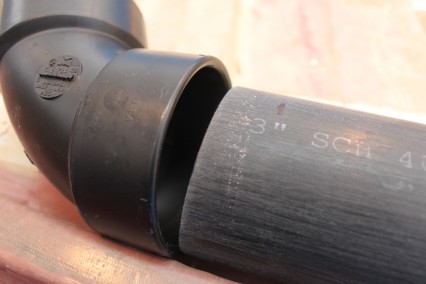
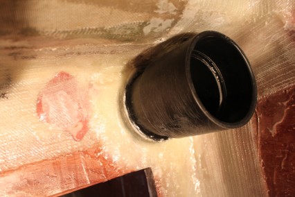
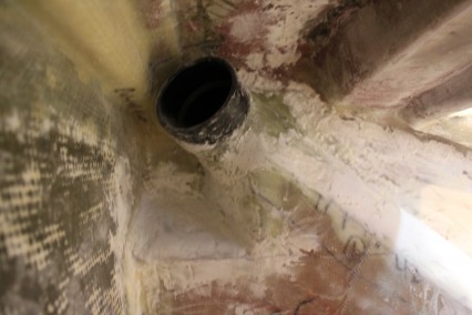
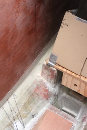
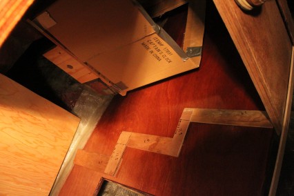
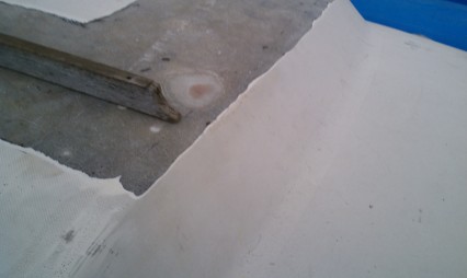
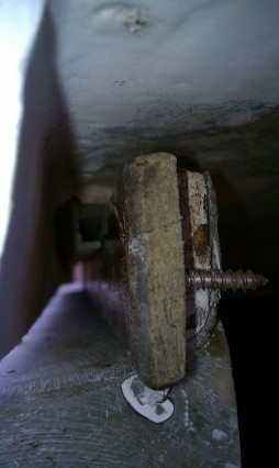
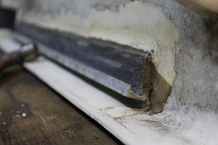
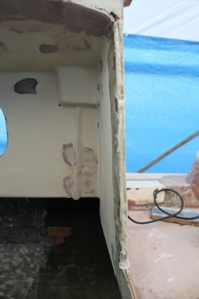
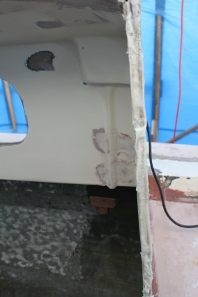
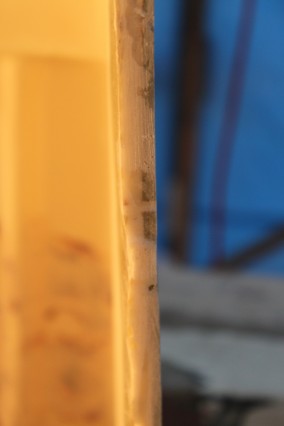
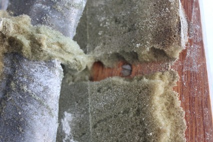
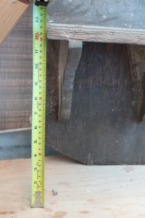
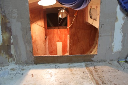
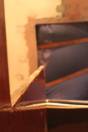
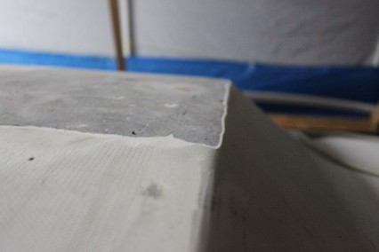
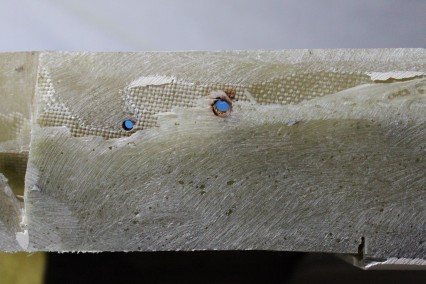
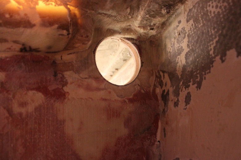
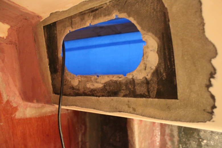
- Drill Through Bulkhead Holes – I first drilled the holes for which the 3.5″ ABS would fit through. There were 4 holes total and each hole represented a location where the engine ventilation needed to pass through a bulkhead. I bought a brand new 4″ hole drill which made very clean and well matched holes for the 3.5″ ABS. Here’s an image of the hole for the ABS:
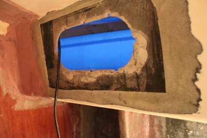
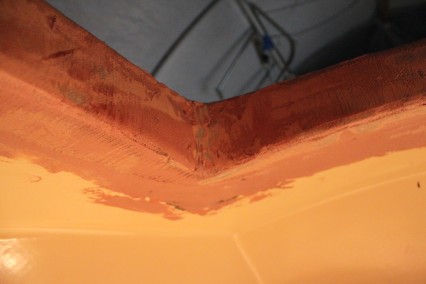
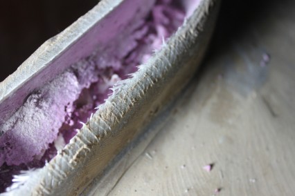
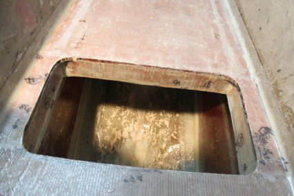
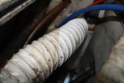
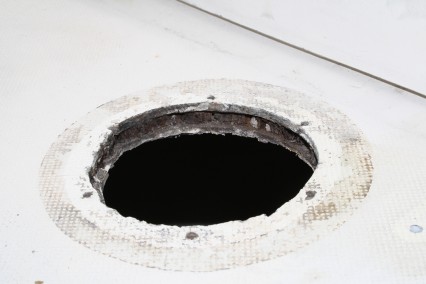
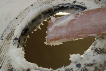
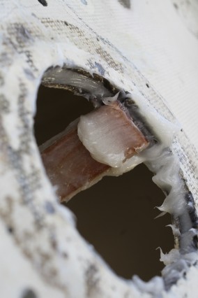
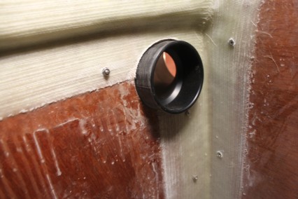
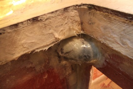
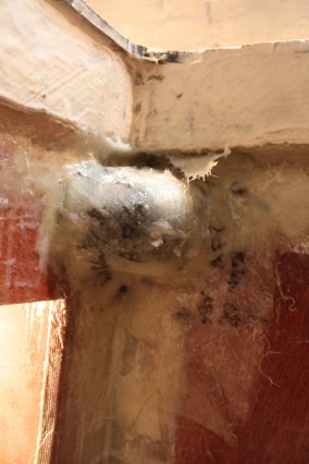
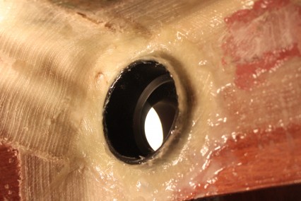
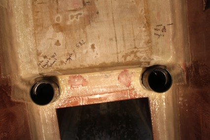
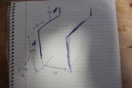
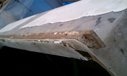
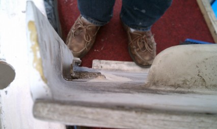
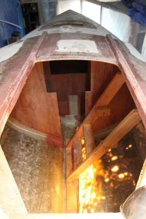
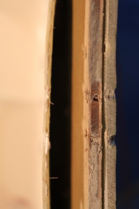
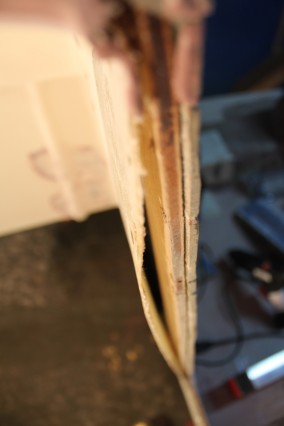
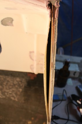
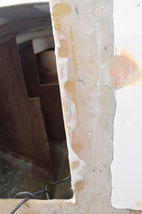
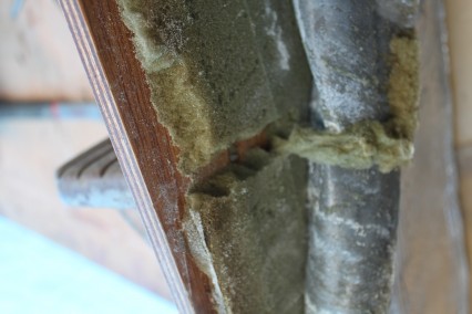
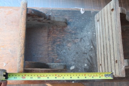
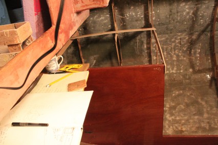
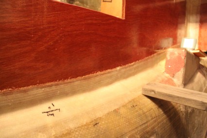
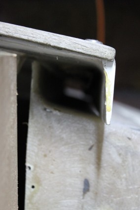
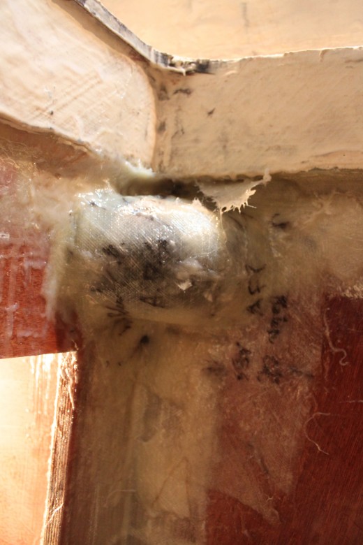
- Fiberglass ABS– With the holes drilled, I then placed all of the ABS loosely in the holes. After cutting fiberglass to fit, I thickened the ABS in place, then glassed the ABS as well. By fiberglassing these through bulkhead connections, I make the connection water-tight around the ABS. Hypothetically, this means that the lazarette and stern lockers shouldn’t allow any water below decks unless they are filled to the brim with water (an unlikely situation and if it did happen, it’s like the boat would already be lost anyway). Below I’ve included an image of what the ABS looked like in one of the harder to glass areas. You’ll notice some areas where the fiberglass overhangs the pipe, but this isn’t much of an issue because after it hardens, I use an oscillating multi-tool and some 60 grit sandpaper to trim off the excess glass. Here’s the image:
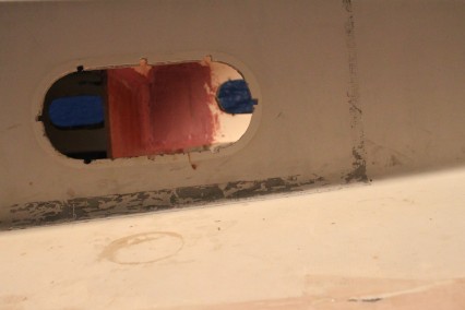
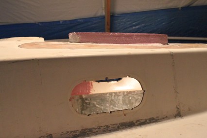
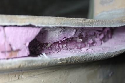
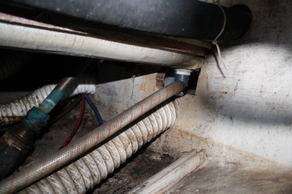
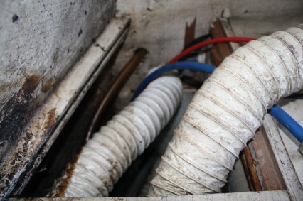
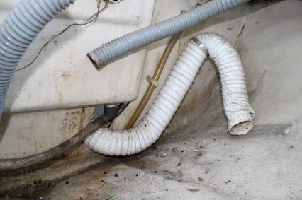
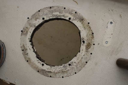
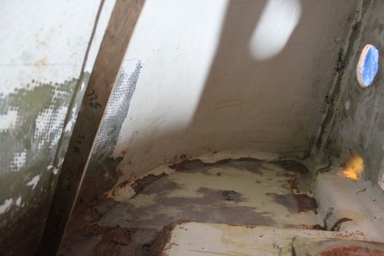
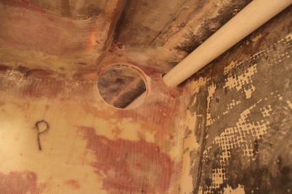
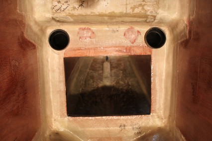
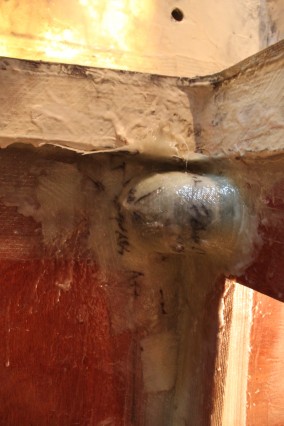
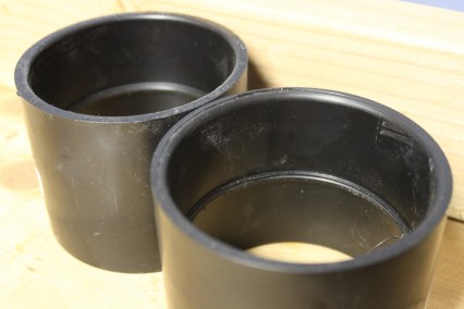
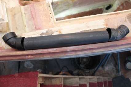
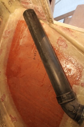
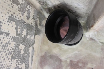
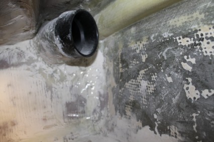
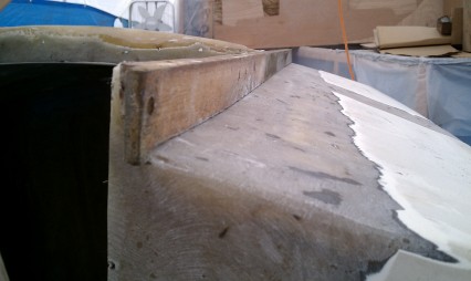
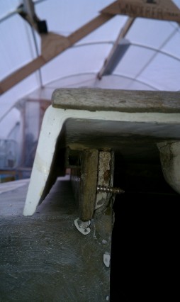
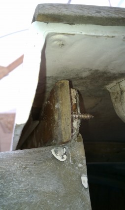
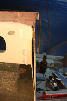
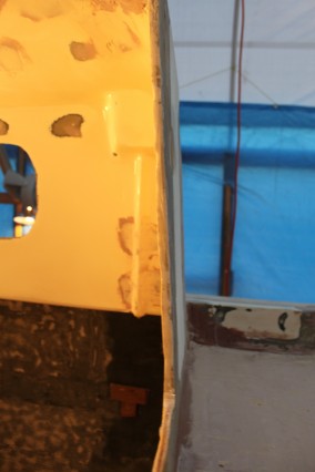
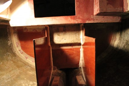
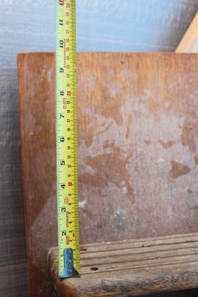
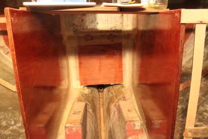
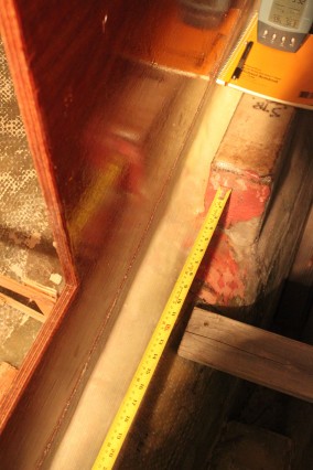
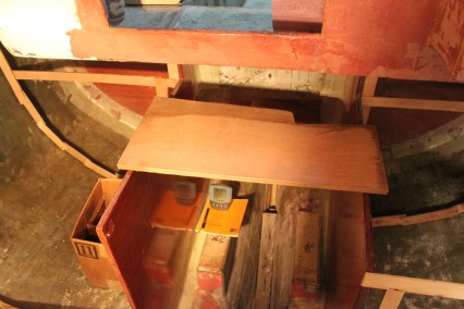
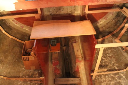
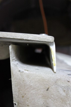
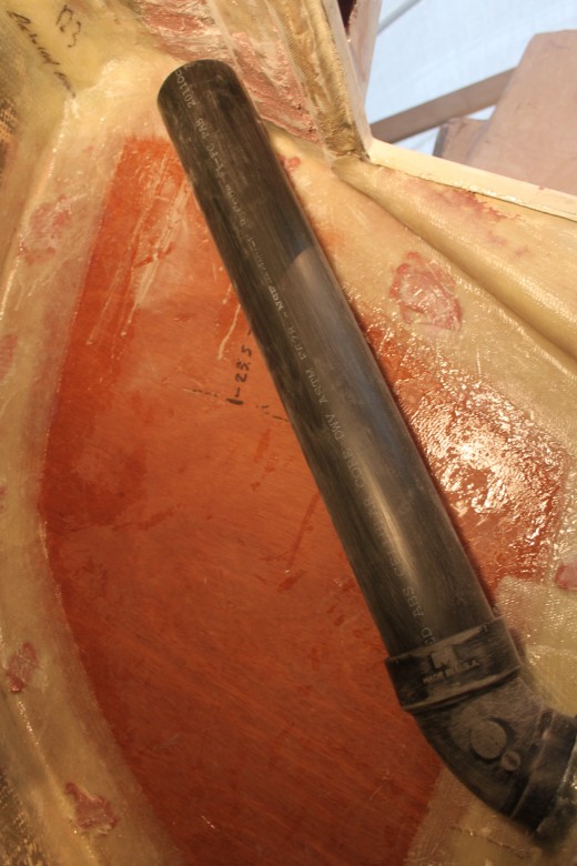
- Glue Additional ABS Runs – With the bulkhead connections in place, I was then able to extend the ABS runs where necessary. There were three key locations where this needed to happen: 2 in the each sea locker (4 total) and 2 connections in the engine compartment. Each through bulkhead connection mean gluing additional ABS to the through bulkhead ABS fitting I had previously installed. In the case of the engine room and through-lazarette connections, this additional ABS was simply meant to allow an easy connection for hose ducting. However, for the connection point in the lower part of the sea locker, the connection allowed me to raise the height of the air intake. This way, if water ever flooded a sea locker, it would have to fill the locker all the way to the top before any water would flood into the engine room. Here’s an image of the lower sea locker connection glued in place (note how the ABS is sanded roughly so as to prepare the surface for future glass work):
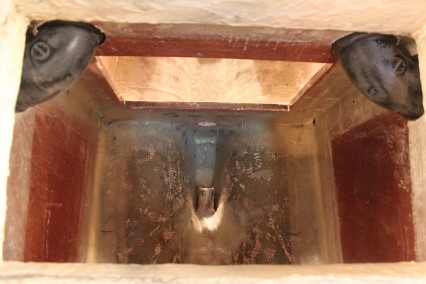
- Fiberglass ABS Runs – After the runs were glued in place, I then poured foam behind the lower sea locker runs, cut the glass for all 6 ABS runs and glassed them all in place. I don’t have an image of these pieces all glassed in at this time, so that will have to wait for a later update.
September 24, 2011
The companionway is still a bit unclear, but the options for how it will come together are being narrowed down (especially with the construction of the cabin sole being completed). I’m looking forward to building this area out, but I’m going to move to the major deck construction projects prior to continuing work inside the boat.
August 8, 2011
As the cabin sole comes together, I am getting a more and more clear picture of how the companionway will come together. I’m not quite sure when I’ll actually begin construction on this portion of the boat, but when I do this area will be updated.
July 14, 2011
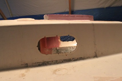
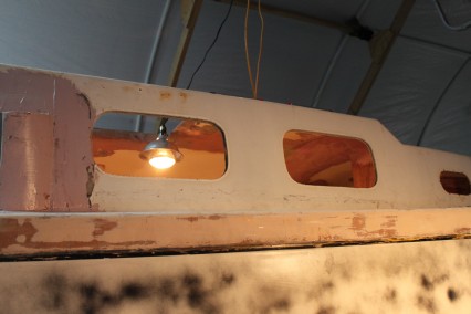
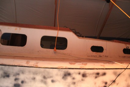
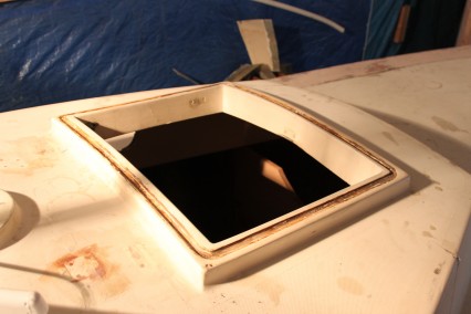
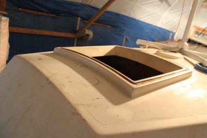
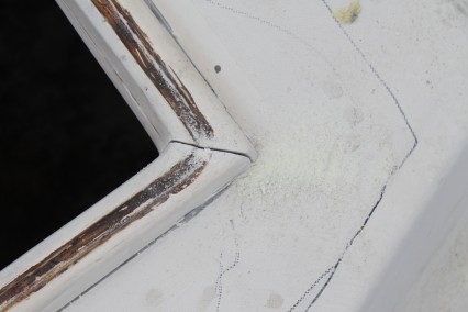
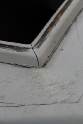
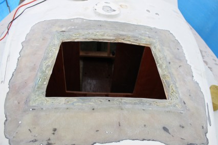
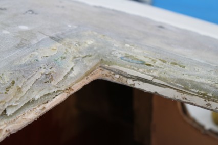
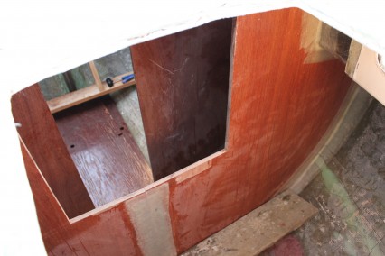
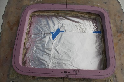
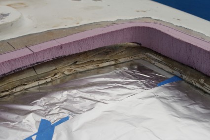
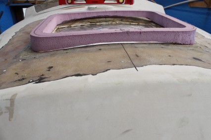
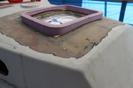
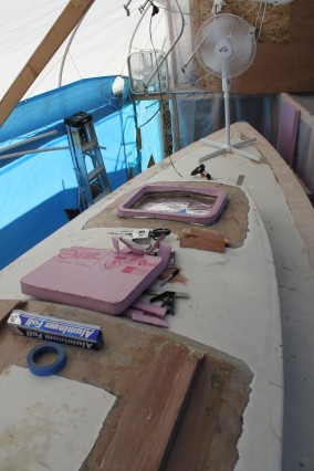
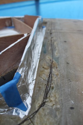
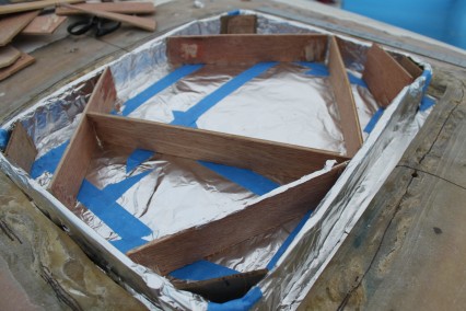
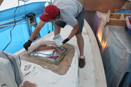
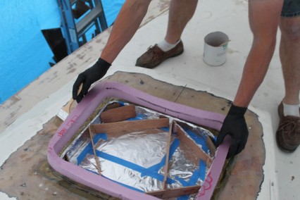
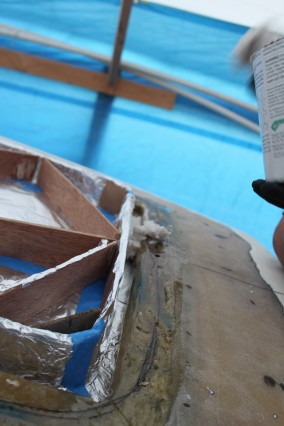
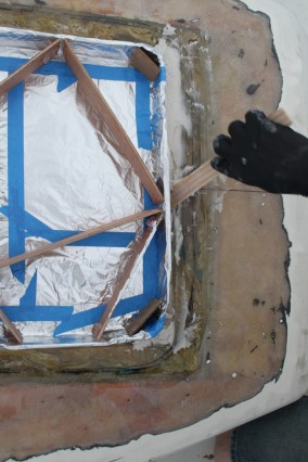
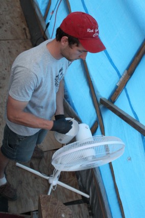
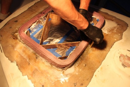
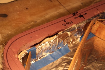
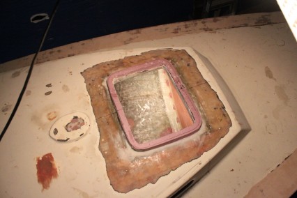
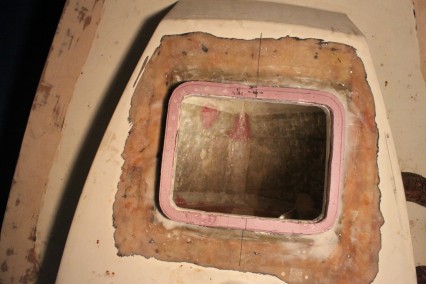
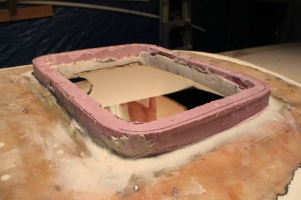
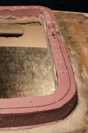
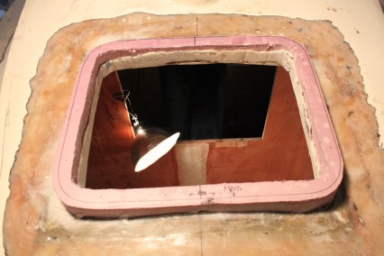
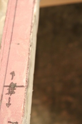
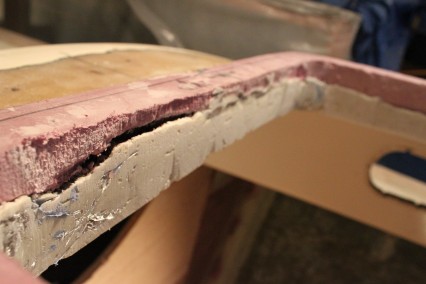
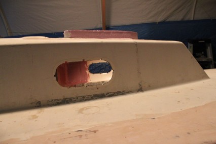
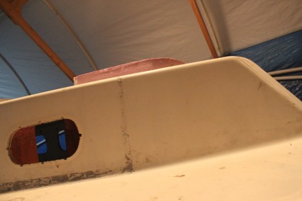
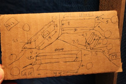
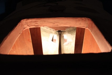
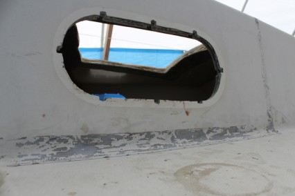
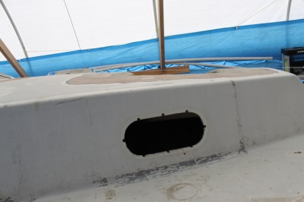
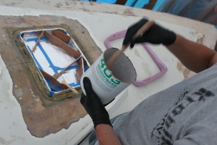
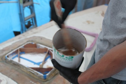
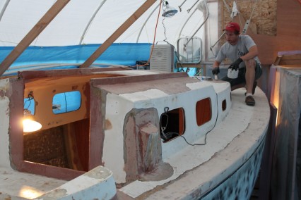
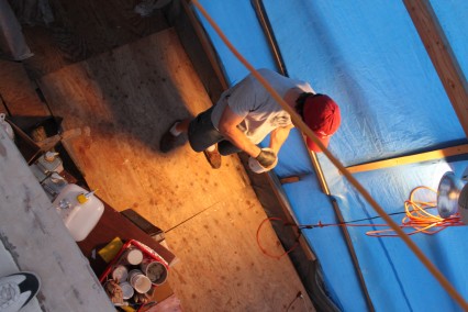
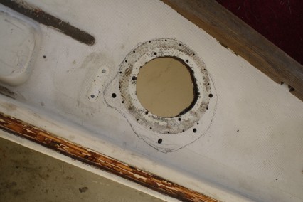
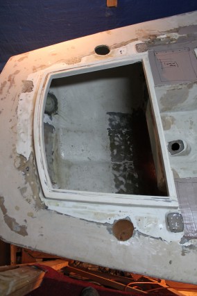
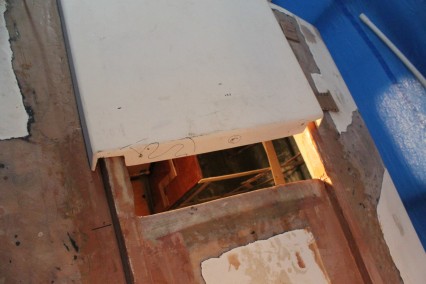
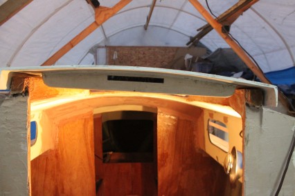
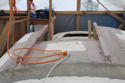
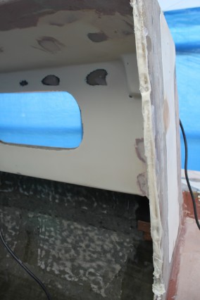
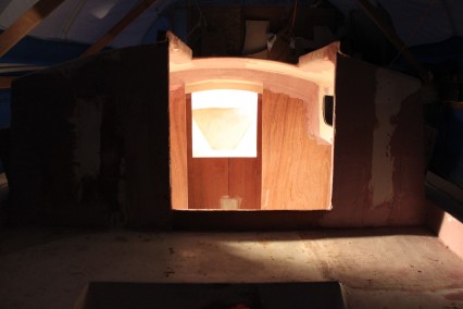
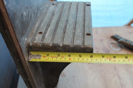
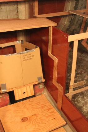
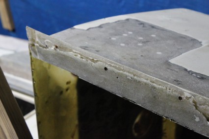
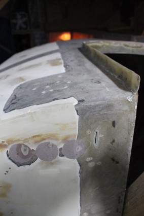
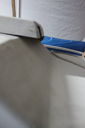
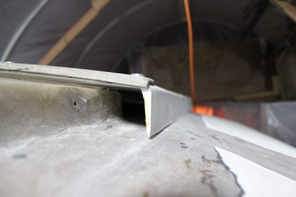
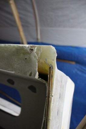
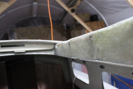
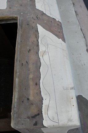
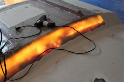
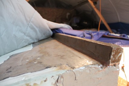
At this time, I’m holding off on working too much on the portlights until I’ve completed the construction of the filler pieces. For most port lights, there needs to be some kind of spacer added to account for the different between a sailboat’s cabin side and the thickness of the port light spigot. In my case, I will create this spacer out of structural foam and fiberglass. Often times this piece is made of teak or a hard wood of some kind, however I’ve decided to go with foam and fiberglass because it will greatly strengthen the cabin sides as well as require no maintenance moving forward. Below is an image show preparation for installing the portlights:
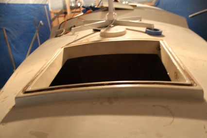
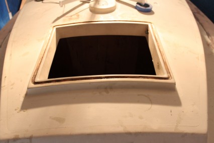
I’m also only working on the interior of the boat, so construction of the seahood will come at a later date, but I do have a good plan how that construction will come together.
Research
- CFM = Cubic Feet per Minute
- The ventilation system of an offshore racing-cruising yacht is both a safety and a comfort device. Not only should the dodger, vents, hatches, and ports be able to rid the boat of noxious and flammable flames, they must provide plenty of fresh air at a comfortable temperature and humidity to keep the cabin free of cooking, body, head, smoking and other odors…the crew must have an understanding of how all these parts work together to form a ventilation system. (Desirable and Undesirable Characteristics of Offshore Yachts, p. 145)
- Working together or alone, the companionway and vents provide air flow to vent engine compartments, cabins, galleys, heads, and lockers. The important thing to remember is that good ventilation depends on good flow of air, and for air to flow below there must be a system of inlets and outlets handling the same amount of air – some facing into the wind to take air in, others facing downwind to exhaust the same amount of air out of the boat. Theoretically, if the dodger and vents are all set to exhaust, no air can get in and there will be no ventilation. Conversely, if all vents are inlets, no air can get out. (Desirable and Undesirable Characteristics of Offshore Yachts, p. 145 – 6)
- See image from Desirable and Undesirable Characteristics of Offshore Yachts, p. 147
- Since ultraviolet rays from the sun will kill body-odor bacteria you can improve the atmosphere below by hanging your smelly clothes in the sun when the chance arises. (Desirable and Undesirable Characteristics of Offshore Yachts, p. 154 -5)
- Ventilating the cabin areas is vital to a dry, mildew-free living area that also is cool in hot weather….A closed boat soon develops condensation or retains humidity from breathing, cooking, lamps and wet clothing. And nothing dries out in dampness like the movement of air, which causes the water to evaporate. Therefore, good cross-flow of air should be planned from the forepeak to the farthest accessible end of the boat. Fresh air also is of value in minimizing the effects of seasickness when holed up below. (Upgrading the Cruising Sailboat, p. 160)
- There is no difficulty getting air out of the boat…but in rough weather, the key to good ventilation is getting air in without water. A lazarette hatch raised to a 35-degree angle provides a very effective forced intake for the after part of the boat (assuming that air passages exist through the bulkheads under the cockpit) (Desirable and Undesirable Characteristics of Offshore Yachts, p. 156)
- The two factors that most determine the amount of air that can be sucked below are the cowl size and wind strength….for each person there should be an air supply of at least 10 cubic feet per minute (CFM) and preferably 15 CFM. The standard used to indicate vent size is the diameter of the deck plate….there should be at least 1 square inch of intake for approximately every square foot of area to be ventilated. Anything less than this 1:1 ratio is unsatisfactory for rough weather offshore. For warm weather, this ratio should exceed 1.5:1. (Desirable and Undesirable Characteristics of Offshore Yachts, p. 150)
- See table from Desirable and Undesirable Characteristics of Offshore Yachts, p. 150 for air flow CFM
- Figuring out how much ventilation is required on a singlehanded boat is relatively simple. Any combination that totals more than 15 CFM should do. In heavy weather at sea, we can assume that wind velocity will be greater than 16 knots. In a rainstorm, however, the wind often is much weaker – about 4 knots. (Desirable and Undesirable Characteristics of Offshore Yachts)
- There is quite a science to ventilation. To work well, the openings on the boat that are bringing in air must be counterbalanced by openings that exhaust it; without this, the air flow stalls out. Crudely speaking, if a hatch, ventilator or canvas structure (e.g.,a dodger) sticks up into the airflow past the boat in such a way that it deflects air downward, it brings air into the boat; if the same device deflects air upward it creates a low pressure (a partial vacuum) in the boat, sucking air out. Knowing this, the trick is to create the desired airflow through the boat in a variety of different conditions, including at anchor, in a marina, at sea, and when the boat is laid up. (Cruising Handbook, p. 124)
- The biggest source of heat in the boat is the galley. On a hot day, you’re trying to keep as much of that heat out of the boat, and on a chilly day, you’re trying to keep it in. Without air conditioning or an auxiliary heater, the cooking heat takes on a bigger role in staying comfortable. On hot days, try to use the stove or oven as little as possible: eat cold foods, cook on the grill and if you do use the stove, pick foods that cook fast (for example, choose pasta over slow-cooking brown rice). A couple of good 12-volt fans and a wind scoop will help, too. Cold days are the time to indulge your cooking desires: make soups and stews that need to cook for a long time, and bake bread and cookies. You can eat well while staying warm! (http://theboatgalley.com/boat-cooking/)
Cockpit Sole Hatch
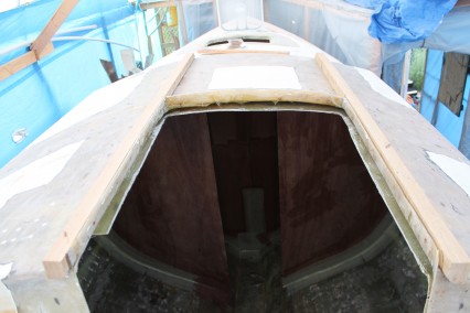
- Whether this hatch will be hinged or lift up, the coamings make it absolutely watertight (see images from same pages as source). This feature requires the lower bedlog to be of 1 ¾” stock. Then ¾” high lips on it shuld be high enough to stop all the water and low enough to remain not too fragile. The inner coaming should be 1 inch higher than the first bedlog. Then if any water makes it past the first one, the inner will surely stop it. (From a Bare Hull, p. 331)
- Half-inch drain holes in the four corners of the bedlog will easily let brave water drops drain away. (From a Bare Hull, p. 331)
- The hatch I ordered is a Bomar cast aluminum inspection hatch, part # BOM-C4T1020, available at Hamilton Marine (order #147407; $357.99). The hatch required a 21″ x 12″ opening…machined aluminum, with two large locking dogs on one side of the hatch, and two stainless steel pins on the other side to lock it in place. (http://www.triton381.com/projects/smallprojects/cockpithatch.htm)
- The hatch has one weakness that anyone using this hatch (bomar cast aluminum) should be aware of. There are two pins in the forward edge of the hatch (the opposite side from the latch side) that fit into holes in the frame. The pins are stainless steel (it would have been better if Bomar had used aluminum pins). To prevent corrosion between the two types of metal, be sure to coat the pins and the holes liberally with Lanocote or a similar product. I also plan to coat the neoprene gasket with silicone grease. Once I determined that everything fit properly, I removed the hatch and slipped it into an old pillowcase for protection. (http://www.triton381.com/projects/smallprojects/cockpithatch.htm)
- I continued by placing the hatch in the opening, ensuring that it was centered and otherwise properly positioned, and then drilled small pilot holes at each screw location with a Vix bit (a self-centering, spring-loaded bit designed for this purpose). With the flange screw locations thusly marked, I removed the hatch again and, using a 1/2″ Forstner bit, enlarged the holes at each location, drilling through the top skin and core, but not through the bottom skin. In this manner, I removed all core material from around the eventual screw locations, eliminating the chance that minor leakage could saturate the core. I replaced the flange one more time and taped the deck off around it for protection. Then, I mixed a batch of loosely thickened epoxy and poured some into each of the 1/2″ holes I had drilled, filling them with solid, strengthened epoxy. The screws will penetrate through this epoxy, which is not only strong, but also isolates the screws from the core, preventing any moisture intrusion issues. Since any forces on this hatch will be from above–whether water, persons, or gear–I saw no reason why screws would be insufficient to hold it in place. I left the epoxy to cure overnight, as usual, before continuing with the installation. Once the epoxy had cured, I set the hatch in place temporarily and redrilled the pilot holes for the installation screws, once again using the Vix bit. Then, I installed the hatch in a heavy bed of 3M 101 polysulfide. The underside of the hatch flange features two grooves to ensure sound bedding in all areas. I secured the hatch with #10 x 1-1/4″ screws. I cleaned up the excess caulk, removed the tape, and the job was complete. (http://www.triton381.com/projects/restoration/cockpitstructure3.htm#COCKPIT%20SOLE%20ACCESS%20HATCH)
- The critical thing is to make sure you use marine grade anti-seize on the bolt and hatch threads.The only problem with many hatches is that they never used the anti-seize. (http://www.capedory.org/board/viewtopic.php?t=8204)
- Screwed-to-the-deck hatches are fine on a coastal boat, but on any boat headed offshore, the hatch frame must be through bolted all the way around. If you will be screwing the frame to the deck, take care that you use the correct bit for the screw size. (This Old Boat, p. 95)
- With the hole cut, I removed the core from the immediate area, scraping back about 1/2″. After cleaning, I filled this gap with thickened epoxy. (http://www.triton381.com/projects/restoration/cockpitstructure3.htm#COCKPIT%20SOLE%20ACCESS%20HATCH)
- I marked the shape of the new hatch on the cockpit sole, and made preparations to enlarge the opening as needed. (http://www.triton381.com/projects/restoration/cockpitstructure3.htm#COCKPIT%20SOLE%20ACCESS%20HATCH)
- I made some fine adjustments with a grinder till the hatch flange fit into place. Then, to prepare the opening, I removed 1/2″ or so of the balsa core material from the exposed back edge and filled the resulting gap with thickened epoxy, to seal the opening and prevent any possibility of moisture intrusion through the cutout. (http://www.triton381.com/projects/restoration/cockpitstructure3.htm#COCKPIT%20SOLE%20ACCESS%20HATCH)
- I cut out the hole, dug out the coring around the edges and filled the cavity with thickened epoxy, set the hatch in place and screwed it down. Well, I also drilled the hole for the mount screws with a half inch drill, filled with epoxy, and then re-drilled pilot holes in the new epoxy ‘plugs’ for the mount screws. This prevents further water intrusion into the core. This should always be done and really shouldn’t need to be mentioned every time. (http://www.triton680.com/Cockpit/triton680_cockpit.html)
Companionway
- To prevent flooding of the cabin should the cockpit be filled, the sills of the companionways should be no lower than the lowest point of the coaming. The bottommost drop board should be capable of being secured into the companionway should heavy spray or waves begin to come board from astern.
- …emphasize the need to limit….the extent to which the companionway opening comes down below the level of the coamings. Ideally, the sill will be higher than the lowest point in the combing….it must have a minimal sill. If it does not, even small amount of water running around the cockpit will flow into the accommodation spaces. (Cruising Handbook, p. 91)
- …on boats with bridge decks, the companionway is a popular watchkeeping station that any kind of sill makes uncomfortable. This can be resolved by hinging the lower dropboard aft onto the deck, creating a seat rather than a lift out, or else by having a separate board that sits on the sill to create a seat. (Cruising Handbook, p. 91)
- The companionway should be on the centerline. If not, in the vent of a knockdown or jibe on one tack, there is a risk of the companionway becoming submerged and admitting huge amounts of water. One factor used when calculating the STIX number is the downflooding angle, that is, the angle of heel at which hatches, if left open, start to flood the boat….On a cruising boat it should be greater than 90 degrees and preferably above 100 degrees. (Cruising Handbook, p. 91)
- If the aft side of the cabin is sloped, it is still possible to keep the drop boards in a vertical plane if they are recessed into the companionway slightly. Unfortunately, while less rain may come in with such an arrangement, the ladder is pushed farther forward into the cabin, somewhat decreasing space below.
- …tapered companionway openings caused a number of boats to lose their companionway dropboards (washboards), and subsequently flood. The boards only had to lift an inch or two to come loose and get washed over board. It is better to have a straight sided opening, although this makes it more difficult to get the boards in and out because they have to be taken to the top of the slot (this can be aggravating if they get cockeyes and jam, which they commonly do). In the event that the slot is tapered, there should be some method of securing the boards. (Cruising Handbook, p. 91)
- Almost all companionway drop boards are made with a simple beveled edge for the mating surface between the boards. This joint admits a surprising amount of water when hit by a wave. much better is a rabbeted edge between the boards, so that there is a lip on the inside of the joint.
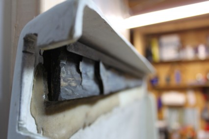
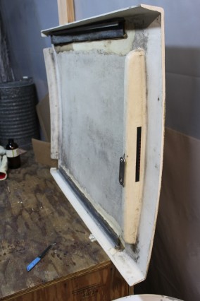
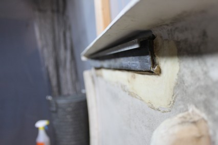
- Upgrading the retaining channels is a good place to start beefing up the main hatch. Protecting against vandals and thieves is an added bonus. Use ¾” thick hardwood. A strip of ⅛” stainless steel thru-bolted to the cabin wall, and locking mechanisms such as barrel bolts on the weather boards are extra insurance against boarding waves, crowbars or the forces that sometimes knock weather board out when the boat is dropped off a hard wave. Inside, a piece of thick teak or other hardwood, several inches wide, should be thru-bolted to the cabin wall. (Upgrading the Cruising Sailboat, p. 161 – 2)
Deck Hatches
- Adding two or four-way opening hatches also aids ventilation. The forward cabin hatch can be modified in this manner, or, if there is sufficient room between the main hatch and mast, an extra hatch can be placed in the ceiling of the main cabin. (Upgrading the Cruising Sailboat, p. 290)
- If the forehatch is hinged on its forward face…with wind coming from ahead (as it will be most times at anchor), the hatch deflects the airflow upward – thereby creating a low pressure – and sucks air out of the boat. If the boat has a similar hatch in the saloon that opens on its aft edge, it deflects the airflow down into the boat. The net effect so far is to create an airflow down into the saloon and out the forecabin. However, if a dodger is in place, its likely effect will be to create a low pressure of the companionway hatch, diverting much of the flow through the saloon hatch aft. (Cruising Handbook, p. 125 -6)
- The foremost hatch should hinge on its forward face so that if a wave comes aboard when it is open, it will be knocked closed rather than ripped off. (Cruising Handbook, p. 94)
- At first sight, the [forward] hatch hinged on its forward edge seems to interfere with airflow, but as long as a windscoop is in use, the reverse is true; in fact, if there is an option about which way to open a hatch, it is best to do it this way. (Cruising Handbook, p. 126)
- We’ve all heard horror stories about people being terrorized by burglars…Suppose you see several men with machetes or guns climbing over the rail. Unless you’re armed…the safest course is to dart back inside and lock all the hatches. Then…call for help. (Upgrading the Cruising Sailboat, p. 78)
- A primary source of ventilation, as well as access for persons sails and stoves, are hatches. But the main companionway hatch is often a weak link in the boat’s armament against boarding seas. Large hatches do make going below easier and do admit more air, but this is no place for compromise. (Upgrading the Cruising Sailboat, p. 161)
- There are five basic requirements for a good main hatch: (Upgrading the Cruising Sailboat, p. 161)
- it should be small – not much more than shoulder width;
- the weather boards should be solid hardwood or plywood, preferably ¾” thick, or Lexan
- as water tight as possible
- the retaining channels that hold the weather boards must be very strong
- There should be devices to lock the hatch inside and outside.
- When equipped with good gaskets and dogs, these hatches can act both as skylights and as vents (as, in the case of the forward hatch, as a passageway for crew, sails, and gear). Preferably the hatch should have hinges fore and aft so it can be opened in either direction to be used as either an intake or an exhaust. (Desirable and Undesirable Characteristics of Offshore Yachts)
- The hatch sides should be straight (with no flare) and should be close to the deck when the hatch is closed so that lines won’t catch under them…in particular, the corners of forward hatches can easily snag a jib sheet during a tack or jibe. A sheet under great strain may bend up a hatch corner, which will leave a gap…so make sure all hatches are dogged loosed (or left all the way open) before tacking. If there’s any change that a hatch corner will hook a sheet even when the hatch is closed, install a guard at the corners. (Desirable and Undesirable Characteristics of Offshore Yachts)
- All hatches should be installed as close to the centerline as possible (in the event of a knockdown, an open, off-center hatch can let in a huge amount of water in a very short period). (Cruising Handbook, p. 94)
- I like to see aluminum-framed hatches installed on a molded-in, raised base because the base helps deflect water away from the seals.
- Mask the deck around the perimeter of the hatch and mask the edge of the flange. You can let the tape stand vertical; its purpose is to keep sealant squeeze-out off the frame. Remove the hatch and completely coat the deck between the tape and the cutout with sealant. Use polysulfide if the hatch frame is metal…Put the hatch back over the cutout and wiggle it gently to distribute the sealant. Insert the bolts or screws and snug them all. Now tighten them, following a patter of each screw in sequence being as opposite as possible to one before (e.g. right side, left side, front right, rear left, etc.) Tighten enough for some sealant to squeeze out around the full perimeter of the flange. Do not over tighten the screws or you will squeeze out all the sealant and the resulting metal to fiberglass joint will soon leak. Allow polysulfide to cure a week, then tighten the nuts on the through-bolts about half a turn to put the sealant under compression. Do not tight screws or you will break the seal on them. Trace a razor knife around the perimeter of the hatch frame to separate the squeeze-out from the sealant under the frame. Peel the tape from the deck and the excess sealant will come with it. Finally, install the trim ring below. (This Old Boat, p. 95)
Deck Prisms
- Skylights, ports, and well-bedded flush deck prisms can provide adequate light in the cabins and head, particularly if the interior is mostly white. (Desirable and Undesirable Characteristics of Offshore Yachts)
- Deck prisms do a remarkable job of adding light below without the obstruction typical of hatches. You can make your own from Lexan, and if you don’t want to see through, wet sand the surfaces to make them translucent….Use a polysulfide or equivalent bedding compound and apply liberally between the flange and deck. If it oozes out when the flanges are bolted down tight, then you know you’ve used enough. Excess compound can be cut away after it has hardened. (Upgrading the Cruising Sailboat, p. 166 – 7)
Dodger Ventilation
- the dodger is often thought of solely as a devise that keeps the cockpit dry…but it has another extremely valuable function. With the help of a good dodger, the typical main companionway is the main actor in the boat’s ventilation system. When the wind is forward to the beam, it serves as a huge exhaust, removing as much air as all the hatches, vents, and other devices combined can take in. When the wind is aft, it scoops in great amounts of air that is exhausted through other devices. (Desirable and Undesirable Characteristics of Offshore Yachts, p. 148)
- Good ventilation is key….The station wagon effect, which can lead to deadly exhaust fumes being sucked into the cockpit. It can be minimized by partially opening a flap in the face of the dodger to ensure an airflow through the dodger. This helps equalize air pressure on both sides of the dodger, thereby stopping the exhaust gases from being sucked in…created anytime the boat is powering into the wind. Unless ventilation flaps in the forward face of the dodger are opened, there will be a slight vacuum behind the dodger, into which the engine exhaust gases may be drawn. At best, this is simply unpleasant; at worst, it can result in carbon monoxide poisoning. (Cruising Handbook, p. 89)
Dorades
- …in spite of all the theory, one well-aimed driving wave can make a Dorade vent act like a fire-hose nozzle…and in any case, another Dorade vent means one more obstacle on deck, and one more deck plate to forget. (Desirable and Undesirable Characteristics of Offshore Yachts, p. 148)
- Dorade-type vents are the main source of fresh air in heavy weather, when portholes, skylights, small hatches, and even the companionway are closed, and when non-baffled vents will take on considerable amount of water…in heavy, relatively calm rainstorm, these vents may provide the only fresh air, since most other openings cannot be protected by dodgers or rain shields…much depends on the cowl vents. (Desirable and Undesirable Characteristics of Offshore Yachts, p. 150)
- Baffled vent, while not as efficient as the Dorade, can work well in drier parts of the deck. (Desirable and Undesirable Characteristics of Offshore Yachts, p. 154)
- At sea…the only effective ventilation is provided by baffled cowl vents, commonly known as Dorade vents….In really rough weather, even a dorade needs closing off, which is accomplished by unscrewing the cowl and replacing it with a deckplate (Cruising Handbook, p. 128)
- For an image of dorade design, see Cruising Handbook, p. 129)
- Dorade vents are more or less essential equipment on a well found cruising boat. Ideally, there will be at least a couple forward and another couple aft. Better yet, is one over every berth, in the galey, and in the head. If the forward and aft vents are set up to face in opposite directions – regardless of the direction from which the wind is coming – there will be a reasonable airflow through the boat.
- …key part of the system is a baffled cowl vent, which keeps air flowing into the cabin while separating out most water. The most reliable baffled vent is the one known as the “Dorade” vent… (Desirable and Undesirable Characteristics of Offshore Yachts, p. 145)
Engine Ventilation
- An inquiry to Perkins revealed that a M60 in a temperate climate should have a duct diameter of at least 16 square inches. In a hot climate, the duct diameter recommendation grows to 32 square inches…Perkins also indicated that the minimum combustion air flow for the engine was 106 cubic feet per minute (CFM). Ideally, the engine would receive 247 CFM of air for combustion and ventilation. The 32 sq. inch cutouts required for proper passive ventilation would be bigger than I would be comfortable installing in the rear…pipes also go through all sorts of convolutions to keep out water – further restricting air flow by increasing pressure drop. (http://www.vonwentzel.net/Prout/01.Propulsion/02.Air/index.html)
- Once we had installed the blowers, our engine was able to rev 200-400 RPM higher than it could before under no-load, while loaded performance improved remarkably as well. Evidently, the air restriction had held back our engine when it was hunkering down driving both propellers….only criticism I have for the blowers is the noise – they were the loudest thing you could hear in the rear cabins when the engine is idling until we dampened their mounting…install a RC circuit to keep the blowers running a bit longer after the engine was shut down. This is to ensure that the alternator is cooled somewhat after coming to a stop. (http://www.vonwentzel.net/Prout/01.Propulsion/02.Air/index.html)
- Also, be sure there’s plenty of air space for your diesel to breathe. You don’t want it to suffocate. Additional air space is also good around your alternator, so that it can cool efficiently…at least the overall engine room is large (meaning there’s plenty of combustion and cooling air available regardless of where the front of the engine box is). (https://docs7.google.com/document/d/1HMve5XJn8STc7FbtxkLuTIruxeQcX7N0LNKzT5-4LlE/edit?hl=en&pli=1)
- When running, engines act as their own exhaust fans by taking in air from the engine compartment and blowing it out through the engine exhaust system. Still, while requirements for ventilation for diesel engines are much less stringent than those for gasoline engines, it’s a good idea to have a system that includes a blower and two large natural-draft vents leading from deck to the engine compartment through clam-shell vents and large diameter tubing. One vent will serve as intake, the other will serve as exhaust. (Desirable and Undesirable Characteristics of Offshore Yachts, p. 155)
- …a diesel engine requires a substantial supply of fresh air for combustion. The minimum air vent size, in square inches, can be estimated by dividing 3.3 into the horsepower rating (e.g., 50 / 3.3 = 15 square inches for our 50 hp Yanmar; to find the vent size in square centimeters, multiply the horsepower by 2, e.g., 50 x 2 = 100 sq. cm). Thought has to be given how to duct in this air with the least impact on the insulation (Cruising Handbook, p. 209)
- Good insulation also traps heat…(the engine room remains hot long after the engine is shut down, slowly feeling its heat into the rest of the boat), but also because it lowers the efficiency of the engine. Although it is rarely done with diesel engines, sometimes it is worth installing an engine-room blower specifically to get rid of as much of the heat as possible….Should it blow in or suck out? If the blower sucks out, the hot air can be directed away from accommodation spaces. However, in this case, there must be a sufficient surface area of inlet-air ducting to ensure that only minimal negative pressure is created in the engine compartment by the blower; otherwise, engine performance will be impaired. On balance, I would have it suck out, with the blower wired to the ignition switch so that it runs whenever the engine is operating – but also wired to a manual override so that it can be kept running for a while after the engine is shut down. (Cruising Handbook, p. 209)
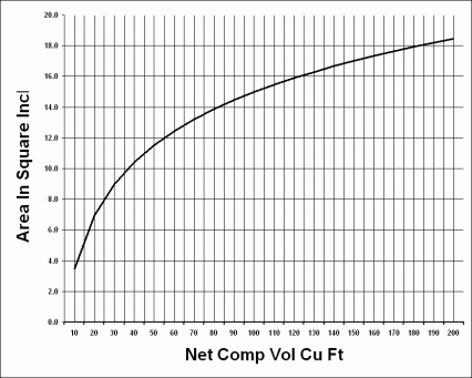
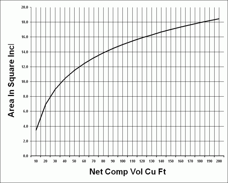
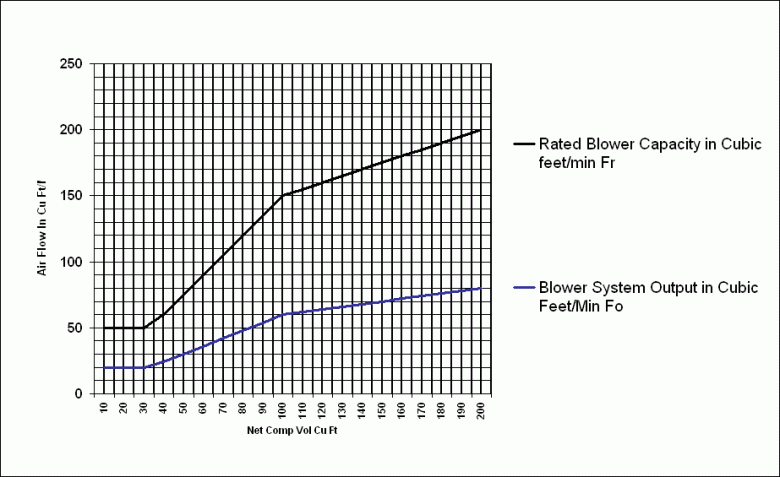
- The Natural Ventilation System must be made up of, at least: A supply opening or duct from the atmosphere or from a ventilated compartment that is ventilated to the atmosphere, and an exhaust opening located on the exterior of the boat….You must have a means to bring in air from the outside and a means to take air out of the compartment, to the outside of the boat. Air in from the outside, air out to the outside. Each exhaust opening must originate in the lower third of the compartment. This is because the fuel vapors collect in the bottom of the boat. So the duct that takes the air out has to begin in the lower part of the compartment.Each supply opening or duct, and exhaust opening or duct must be above the normal accumulation of bilge water. Get it low enough to get the vapors out but not so low it sucks up bilge water.The openings or ducts must be sized to move enough air in and out of the compartment. The absolute minimum size is an opening of 3 (three) square inches….To determine the correct opening size, see graph below and follow these instructions: First, add up the volume of the compartment. Subtract the volume of the engine, battery, fuel tank and any other large equipment in the space. (Generators, flotation blocks etc). Then reading up from the bottom of the graph (compartment volume) go up to the curve, and the read over to the left side of the graph to get area of the opening. You can have more than one exhaust opening and more than one intake opening to meet the requirement. The important thing is airflow. Here’s the graph you can use to follow from the regulations that will help you to figure out the correct size (http://newboatbuilders.com/pages/vent.html):
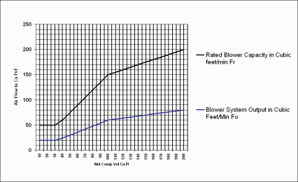
- To help determine the rated capacity of a blower for your system look at this graph of air flow versus compartment volume (http://newboatbuilders.com/pages/vent.html).
- Location of vent openings: Vent openings often have cowlings on themand many times one is pointed forward and the other is point aft. Actually, for natural ventilation this is not necessary. Practical tests have shown that when the boat is standing still the wind direction is what determines which opening is the inlet and which is the outlet. When the boat is moving and the blower is on, the duct that has the blower is the outlet. Also cowlings can often create restrictions in the amount of air flow. Use cowlings that do not reduce the size of the openings. (http://newboatbuilders.com/pages/vent.html)
- Preventing Water Intrusion. One thing you do need to know is that placing the cowls on the side of the boat, or back (transom) of the boat, can result in the boat sinking if water enters the opening. This is not a joke. Numerous boats have been sunk because water came in the vents. If the vent is on the side or transom, route the duct up in a loop, an upside down U shape (in the plumbing world called a P trap) and then down, so the top of the loop is several inches higher than the vent opening, or use a manifold inside the opening and have the duct enter the top of the manifold. Provide a drain from the manifold out the side of the boat to get rid of accumulated water (http://newboatbuilders.com/pages/vent.html)
Fans
- We have 6 fans installed for ventilation, plus 3 more yet to be installed. We like the Caframo ‘Sirroco’ fans in that they move a lot of air, fold flat when not in use, and don’t use much power…installed a ‘Vetus’ ventilator fan in the bulkhead to the head compartment. (http://www.sailvictoriarose.com/Interior.html)
- Electric fans greatly improve comfort below….Small, inexpensive 12-volt, 5 ½” diameter rubber-bladed fans are rated to circulate air at 250 CFM. When located in the galley, main saloon, and sleeping quarters, these fans can provide considerable relief in hot, humid weather. (Desirable and Undesirable Characteristics of Offshore Yachts, p. 153)
Locker Ventilation
- …replac[e] solid cabinet door with louvered ones. Caning should be avoided on the door of any large locker full of heavy objects as a can of tomatoes would have little difficulty busting through… (Upgrading the Cruising Sailboat, p. 77 )
- Lockers – whether for anchor rode or for clothing – should have built-in louvers. (Desirable and Undesirable Characteristics of Offshore Yachts, p. 148)
- To avoid mildew, keep all wet gear in its own lockers, away from dry gear. Louvers also provide an exhaust when set into companionway slat. (Desirable and Undesirable Characteristics of Offshore Yachts, p. 153)
- Lockers and other storage areas may be dampened by condensation long before the rest of the hull. It helps to pack gear loosely to encourage free air to circulate. Good insulation can be a benefit too, because it keeps engine noise and heat from the living area, and prevents heat from passing through the hull and deck. (Desirable and Undesirable Characteristics of Offshore Yachts, p. 150)
- …added cane inserts to every locker door on the boat, so that lockers could “breathe” (cane inserts or louvers should be standard on all cruising boats; doors with solid panels are not acceptable). (Cruising Handbook, p. 124)
Portlights
- Bronze port lights are nearly indestructible. I see thousands of aluminum opening portlights that are more than 20 years old and show no signs of failure or weakness. (This Old Boat, p. 155)
- Maintenance of opening portlights involves little more than rinsing the frames regularly and applying an occasional coat of wax to retard surface corrosion. Lightly lubricate the screw dogs. (This Old Boat, p. 155)
- The part that extends through the cabin side is called the spigot and the flared end of the spigot is called the flange. The frame that slips over the opposite end of the spigot is called the finish ring. Modern designs have the spigot inserted from the outside with the finish ring on the inside. From an engineering standpoint, an outside flange (and inside finishing ring) makes the portlight easier to bed. As a rule you only bed exterior contact surfaces. However, if the finish ring is outside, the sealant must also prevent water from penetrating between the inside perimeter of the ring and the outside surface of the spigot. The best assurance is filling the space between the spigot and the cabin side with a generous application of sealant, carrying the sealant out into the spigot beyond where the finish ring will lie. You must be sure there is sufficient sealant on the ring and the spigot to form a watertight seal between the two components. (This Old Boat, p. 155)
- Ports are especially vulnerable. The safest design for a cabin port is an elongated ellipse. Rectangular ports may seem more attractive, but they are structurally poor because of the abrupt transition between the gross and the net. (Desirable and Undesirable Characteristics of Offshore Yachts, p. 106)
- Portlights aren’t too expensive to purchase and install yourself. I’d opt for bronze ports…They’re a bit more expensive, but much stronger and certainly better looking. A new opening port can be installed where no present port exists, or if the opening port is larger than an existing fixed port, the old one can be removed and an opening one put in it’s place. (Upgrading the Cruising Sailboat, p. 290)
- If the port doesn’t come with a template to mark the size hole to be cut, make one out of cardboard. use a pencil to mark the outline and then drill pilot holes large enough to accept a saber saw blade. Small cutting errors of ⅛” or so can be covered by the port flanges. Be sure to seal off any core material…Us a good quality bedding compound to prevent leaking around the port -surely the most common source of leaks. When the screws are tightened, the compound should ooze out everywhere. (Upgrading the Cruising Sailboat, p. 290 – 1)
- Rainhoods keep rain out when you want the port open for ventilation. You can form your own by heating thin sheets of Plexiglass with a torch. Simple windscoops can be cut from Clorox bottles or any other plastic container that can be jammed into a port. The open end should face onto the cabin; outside on the forward side of the container, cut a large hole to funnel the wind.
- Opening portholes always seem to leak after a few years….To minimize aggravation, the external frames should be designed with drains so that when the boat is on an even keel, there is no puddle of standing water in the frame. In addition, a rail should run around the inside of the cabinside to catch any drips that get through. The rail makes an excellent handhold at exactly the right height for most people to hang onto when the boat is heeled. (Cruising Handbook, p. 94)
- Portholes can provide good cross ventilation and, when equipped with rain shields, may be left open in light rain or spray. However, heavy vertical rain will splash off the deck and into an open port. Like hatches, they require good gaskets and dogs, and must be dogged down with care so they do not snag sheets. (Desirable and Undesirable Characteristics of Offshore Yachts, p. 153)
- Keeping the cabin cool in summer is easier and much less costly than heating in the winter. Good cross ventilation is a starting point. It amazes me that more boats aren’t equipped with opening ports to help accomplish this. A major reason is the cost-cutting measures of boatbuilders. (Upgrading the Cruising Sailboat, p. 290)
- Opening portlights…contribute almost noting to the ventilation of a boat when at anchor. Their contribution can be improved with individual wind scoops… (Cruising Handbook, p. 126 -7)
Seahood
- (For a full walk through on building a sea hood, please refer to pages 171 – 175 of Upgrading the Cruising Sailboat)
- (For another walkthrough, please refer to “A Seahood for Magnolia” article from Practical sailor)
- Aft-facing companionways should be protected with sea hoods and dodgers so that rain, spray, and boarding seas do not find their way below. ( Desirable and Undesirable Characteristics of Offshore Yachts, p. 120 )
Screens
- All vents, ports, and hatches (including the companionway hatch) require easily installed bug screens. We have a screen that drops into the companionway in place of the hatchboards. For security reasons, it is ruggedly constructed with divider bars that break up the screened areas into spaces too small for someone to squeeze into the boat.
- All of the screens, particularly the larger ones, need a designated stowage space where they will be protected from damage when not in use.
- Many portlight bug screens are retained by screws that make the instalation semipermanent. Given that a screen severely limits the airflow (and alos the light), it is preferable to have clip-in screens, which will be used only when needed.
- Since screens reduce ventilation by about 50%, anybody cruising in a hot, buggy area will have to make a sacrifice…For some reason, bugs do not seem to want to swarm down a vent cowl…
Vents
- Cowl vents probably move more air than any other type, but they also present special problems. For one, lines are easily snagged on them. And, as mentioned, they cannot be closed from below without modification. (Desirable and Undesirable Characteristics of Offshore Yachts)
- I prefer the solar vent…or a lower mushroom type that can exhaust by a combination of natural draft and suction created by wind passing over the dome. This type of vent has a screw knob for quick shutoff in very rough weather. (Desirable and Undesirable Characteristics of Offshore Yachts, p. 148)
- The mushroom works well in all but the worst conditions and does wonders in keeping air circulating below. (Upgrading the Cruising Sailboat, p. 160)
- Sometimes, in place of the duct into the boat, a regular mushroom vent is fitted, in which case it too can be closed. The downside is that the mushroom vents are commonly installed on the deck, and therefore, are not as effective at deflecting water as a higher duct; they will need to be closed long before the higher duct. (Cruising Handbook, p. 128)
Comment Form